
A profile drawing can define one formed-metal component. It does not always explain where that component belongs, which way it faces, or how it connects to the pieces around it.
That distinction matters when a request brings together several profiles, changes in direction, curved transitions, stepped details, and adjoining sections. The individual part drawings remain important, but an assembly-level drawing provides the map that connects them.
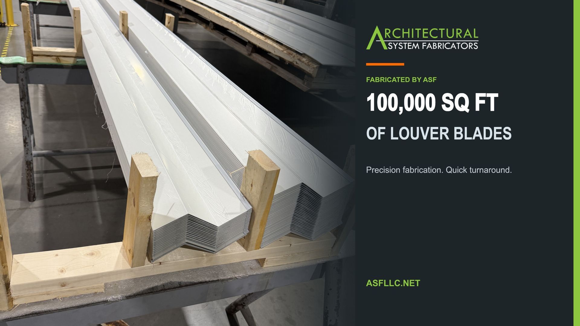
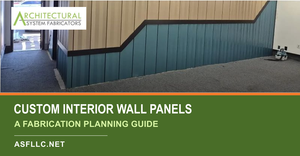
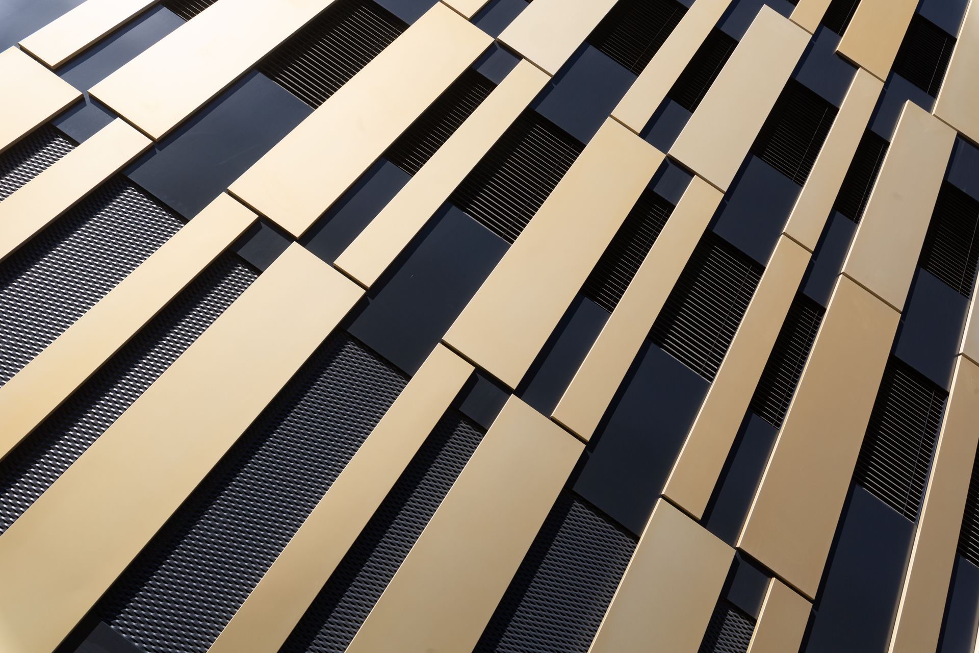
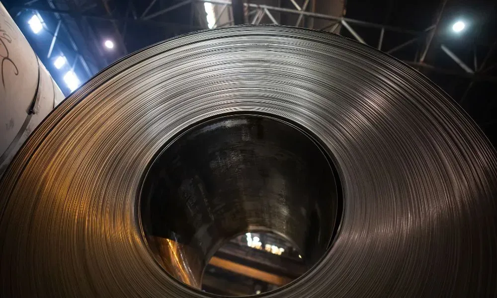
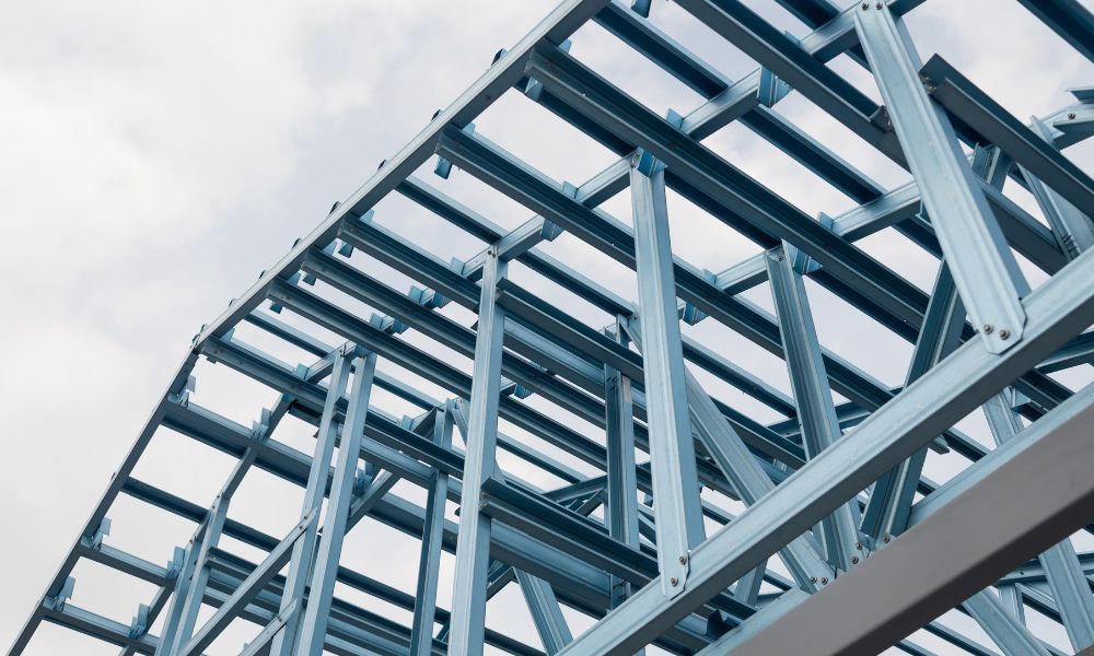
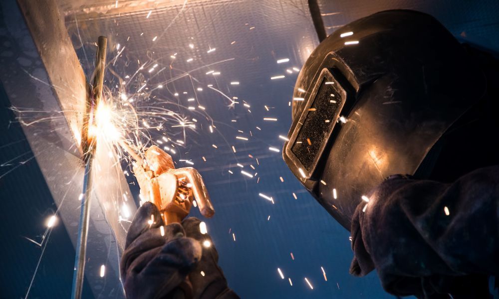
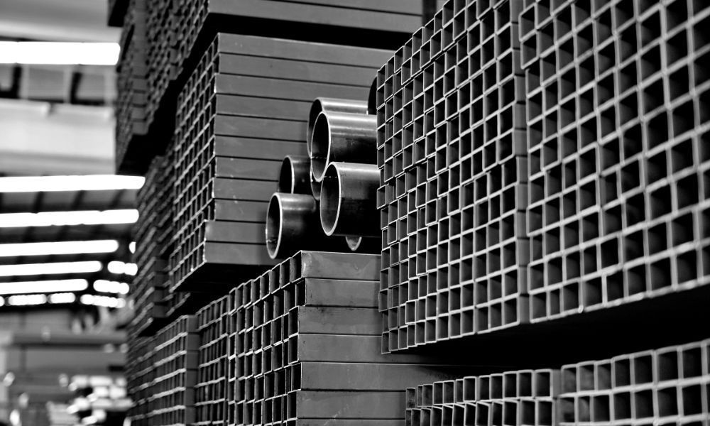
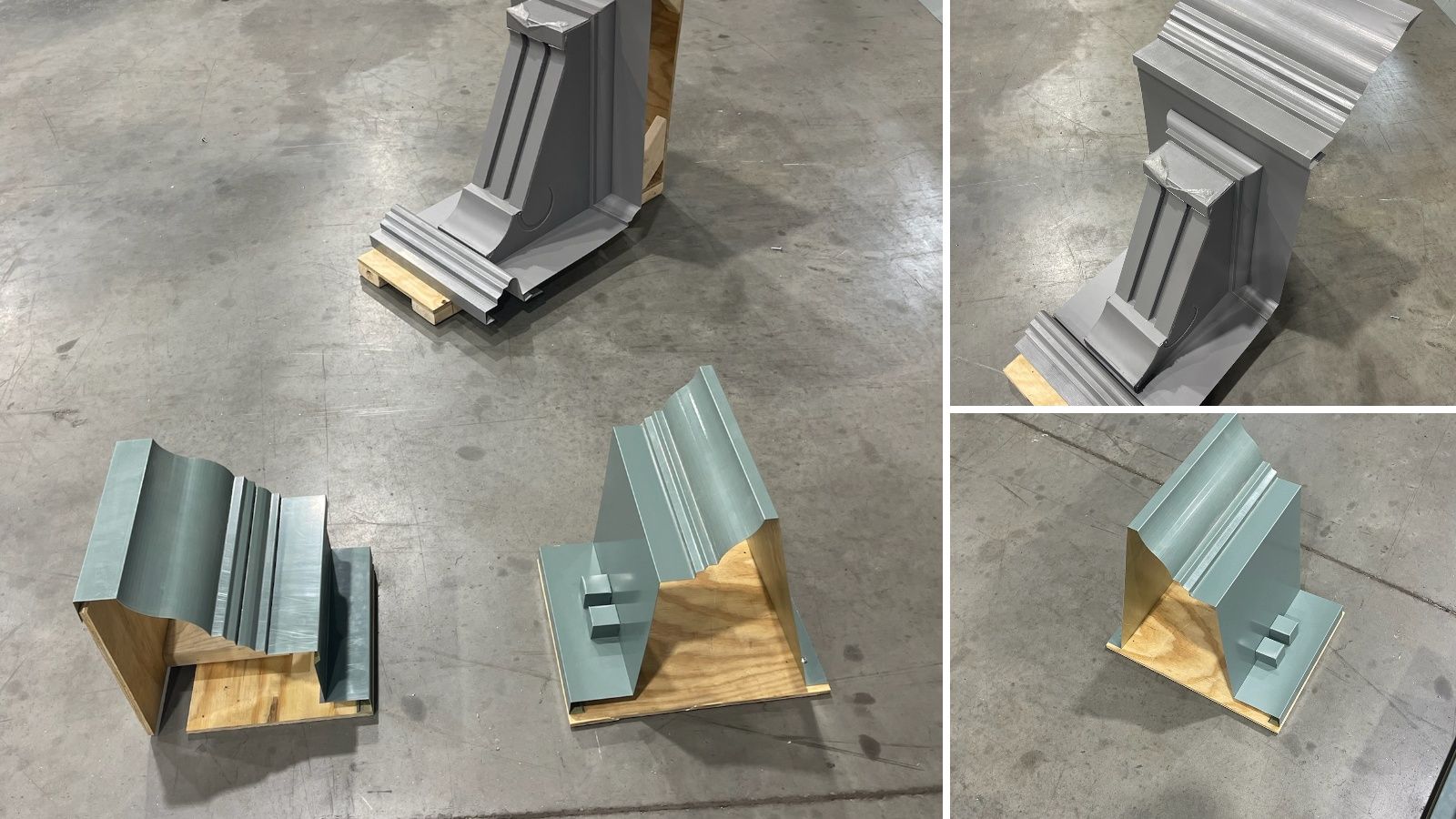
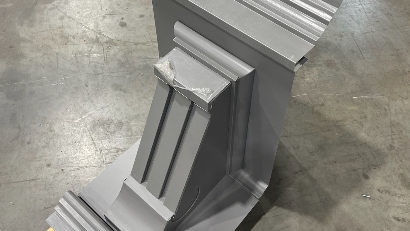
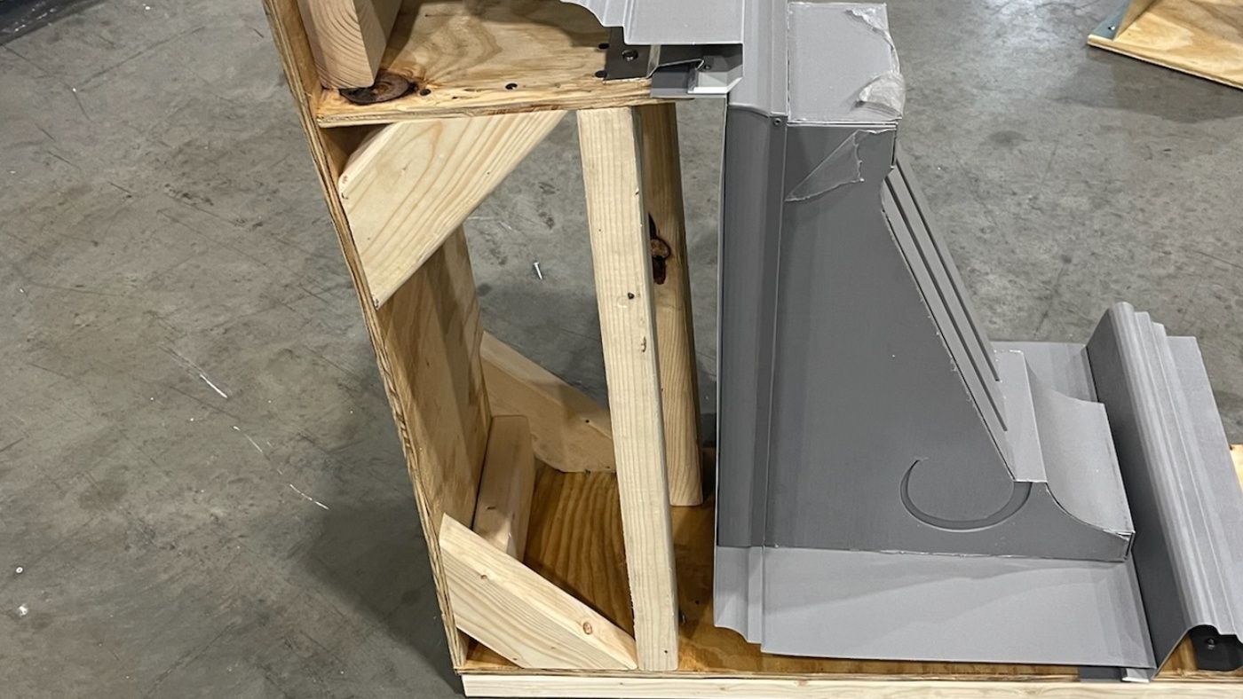
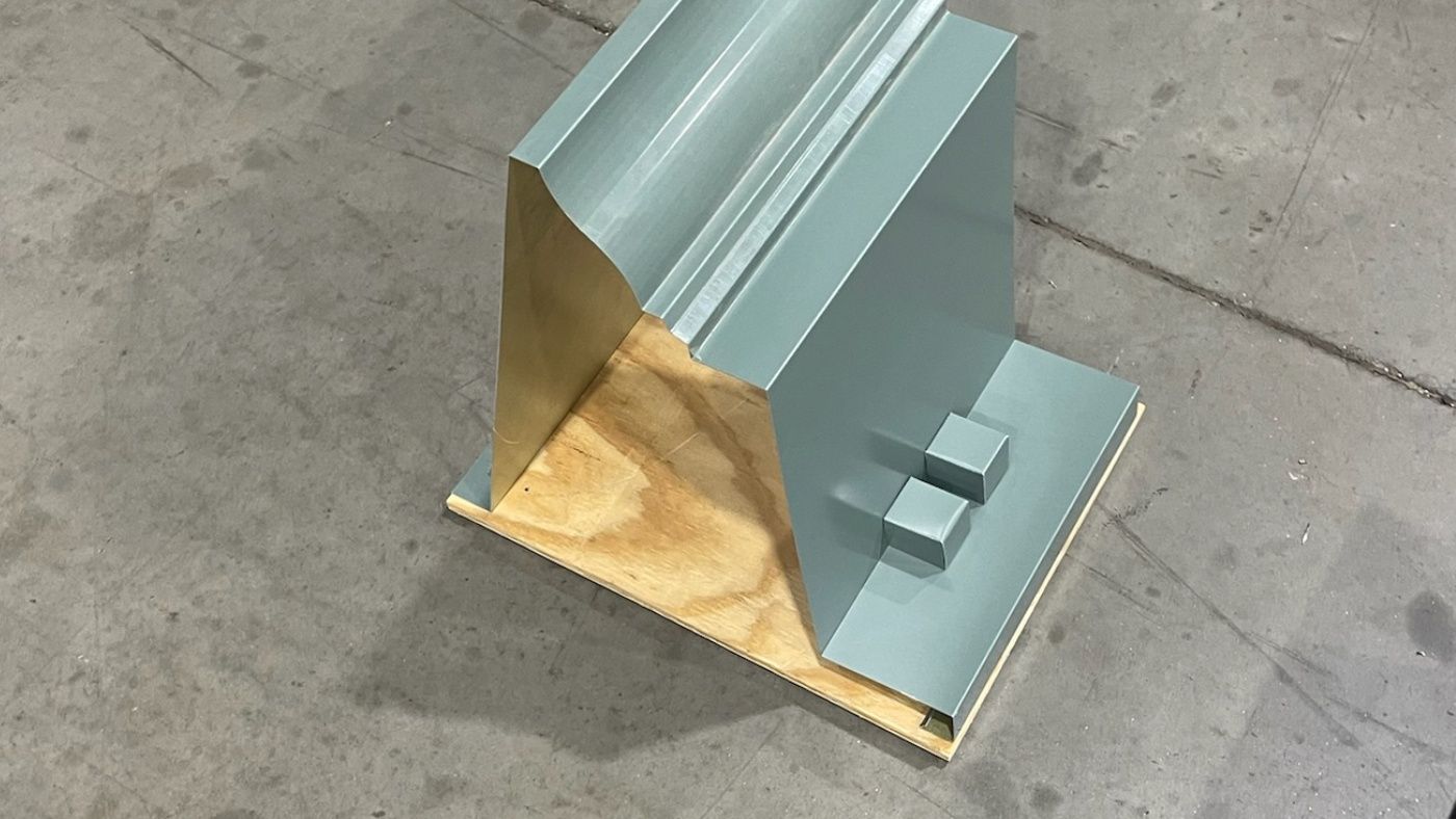
The shop photographs in this article show visible examples of complex formed geometry. They are presented to illustrate the drawing principles below; no customer or project details are included.
One component and one assembly answer different questions
An individual component drawing answers: What is this piece? It can show a cross-section, dimensions, bends, returns, openings, and end conditions.
An assembly-level drawing answers: Where does this piece belong, and how does it relate to everything around it? It should make the component's orientation, neighboring pieces, transition points, and overall position understandable without forcing the reviewer to reconstruct the full condition from separate details.
For complex formed-metal work, both levels of information are useful. The assembly view does not replace the part drawings, and the part drawings do not replace the assembly view.
The overall view creates a component map
Begin with a plan, elevation, three-dimensional view, or other overall drawing that shows the complete condition. Every unique component should have a part mark that also appears on its related detail.
The purpose of this view is not to carry every small dimension. It is to establish the relationships that would otherwise remain scattered across the drawing set:
- Which components belong together
- Where each part starts and stops
- Which pieces repeat and which are unique
- Where the assembly changes direction
- Which sections meet at each transition
- How the condition is oriented in the overall work
When the overview and individual details use the same part marks, a reviewer can move between them without guessing which profile belongs to which location.
Sections explain what happens through a transition
A front view may make a curved or stepped condition look simple even when the profile changes through its depth. Sections and enlarged details can reveal what the overall view cannot.
Place sections before, through, and after an important transition when the cross-section changes. Reference those sections from the assembly view and label them consistently. If the transition is gradual, identify the points that control its beginning, end, and relationship to adjoining geometry.
The goal is not to add drawing complexity for its own sake. It is to reveal the geometry that actually controls how the components relate.
Interface details show where individual profiles become one condition
Interfaces deserve deliberate details. An assembly-level drawing should show where components meet and identify the alignment or relationship the project team expects at that point.
Depending on the design, that may require a plan detail, section, enlarged elevation, or a combination of views. The drawing should make it possible to distinguish a true connection or transition from two unrelated profiles that simply appear close together on the page.
Any surrounding condition that controls the interface should be referenced clearly. ASF provides fabrication services and does not perform field installation. Responsibility for field verification, final coordination, and installation planning should be confirmed within the project team.
Orientation and handedness must remain visible
A correct profile can still be incorrect for a location if its orientation is reversed. Assembly drawings should identify the viewing direction, reference face, and any left-hand, right-hand, or mirrored condition.
Do not rely only on the position of a detail on a sheet. Use orientation marks, section arrows, part marks, or clear notes that continue through the related views. If two pieces share a profile but face different directions, the drawing set should make that difference unmistakable.
Part marks connect the full drawing set
Part marks are most useful when they stay consistent across the assembly view, individual part details, section callouts, schedules, and revision notes. A simple identification system can make a complicated geometry set easier to follow.
Each unique part mark should point to one clearly defined component. Repeated components can share a mark when they are truly identical. Mirrored, handed, or location-specific pieces should remain distinguishable.
This connection between the overall drawing and the individual details helps keep the review focused on the intended relationships, rather than on reconciling inconsistent labels.
Revisions need to move through every connected view
Changing one transition can affect more than one drawing. A revised profile may require updates to the assembly view, neighboring details, section references, part marks, or schedules.
Before a drawing set is treated as current, check that the revision appears in every affected location and that superseded information is clearly withdrawn. A short revision summary can identify which relationships changed and help prevent an earlier condition from remaining active elsewhere in the set.
What should an assembly-level drawing make clear?
A reviewer should be able to answer these questions from the coordinated drawing set:
- What are the individual components?
- Where does each component belong?
- Which way does each component face?
- Where and how does the profile change?
- Which parts meet at each interface?
- Which pieces repeat, mirror, or remain unique?
- Which revision controls the complete condition?
If an answer depends on an assumption, identify it as an open coordination item before fabrication review.
From customer drawings to fabrication review
ASF's capabilities include custom assemblies from customer drawings, drafting and shop drawings, metal fabrication, and metal bending and folding. For complex formed-metal work, an assembly-level drawing helps connect those individual fabrication details to one coordinated condition.
Learn more about ASF's metal fabrication and metal bending and folding capabilities.
Have a complex formed-metal condition to coordinate?
Contact ASF with the current drawings or available details for fabrication review.
Submission is a request for review. It does not confirm feasibility, pricing, material availability, production time, or a production date.